

可用性為 99.9% 的拓撲適用於可容許部分停機時間的非重要應用程式。例如,貴機構可能會進行批次上傳,而其作業的時間點並不重要。如果無法連線,系統會在連線恢復後繼續執行作業。
如要瞭解本頁使用的 Cloud Interconnect 術語,請參閱「重要詞彙」。
如要瞭解如何建立備援 Cloud Interconnect 連線,確保在容錯移轉時有足夠的容量,請參閱「最佳做法」。
需求條件
如要達到 99.9% 的可用性,必須符合下列條件。
您必須設定至少兩個 Dedicated Interconnect 連線,並在單一都會區內的一對設施和邊緣可用性網域組合之間策略性分配:
找出設施和邊緣可用性網域組合:
如果都會區只有一個設施,則設施和邊緣可用性網域組合配對,就是該都會區一個設施中的兩個邊緣可用性網域 (例如
bos-zone1-219和bos-zone2-219)。如果都會區有兩個以上的設施,則有效的設施和邊緣可用性網域組合,會由一個設施中的可用區 1 和另一個設施中的可用區 2 組成 (例如
atl-zone1-3725和atl-zone2-940)。
同時使用設施和邊緣可用性網域組合:在都會區內,至少有一個互連網路連線必須位於一個設施和邊緣可用性網域組合中,且至少有一個互連網路連線必須位於該組合的另一個組合中。
在您建立依賴 Cloud Interconnect 連線的 VLAN 連結時,每個虛擬私有雲網路都必須符合下列要求。
地端部署路由器和路由 advertising 規定
請參閱地端部署路由器的說明文件,瞭解如何設定路由器,以達到 99.9% 的服務水準協議。您可能需要將專屬實體路由器連至各個互連網路連線。
地端部署路由器必須透過各個 VLAN 連結的 BGP 工作階段,advertise 相同的前置字串。您可以使用不同的 BGP 指標 (例如 MED) 來達成連線能力目標。如要進一步瞭解 Cloud Router BGP 工作、動態路由控制層和虛擬私有雲網路控制層如何根據收到的前置字元建立動態路由,請參閱 Cloud Router 說明文件中的「已知路由」。
拓撲範例
下列拓撲範例符合 99.9% 可用性,在下列設施和邊緣可用性網域組合中,有兩個 Cloud Interconnect 連線:
lga-zone1-16lga-zone2-1422
兩個 VLAN 連結 (共同使用兩個互連網路連線) 位於單一虛擬私有雲網路的 us-central1 區域。
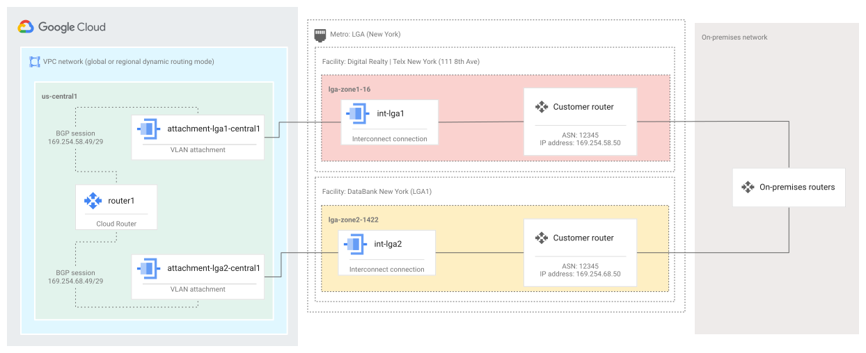
設定偏好路徑
Dedicated Interconnect VLAN 連結會依賴 Cloud Router,從遠端對等互連路由器 (例如地端部署網路中的路由器) 學習前置字元。虛擬私有雲網路的動態轉送模式和最佳路徑選取模式,會控制 Cloud Router 考量哪些下一個躍點,以及如何處理 BGP 屬性,以產生動態路徑。虛擬私有雲網路中的動態路由,定義了從虛擬私有雲網路到已連結網路 (例如地端部署網路) 的路徑。詳情請參閱 Cloud Router 說明文件中的「已學習的路由」。
如要建立從連線網路到虛擬私有雲網路的路徑,請設定 Cloud Router BGP advertise。您可以個別設定每個 BGP 工作階段的 advertisement,或定義 Cloud Router 的預設 advertisement。這些 advertise 項目可以包含子網路範圍、自訂前置字元,或兩者的組合。詳情請參閱 Cloud Router 說明文件中的「advertise 的路由」。
建立 99.9% 拓撲
以下各節將逐步說明建立這個拓撲的步驟。如要建立個人化的拓撲,請使用您自己的值取代範例輸入值。例如,將 vpc1 網路名稱替換為您的虛擬私有雲網路名稱。
訂購 Cloud Interconnect 連線
使用 Cloud de Confiance 控制台或 Google Cloud CLI 訂購重複連線。
控制台
前往 Cloud de Confiance 控制台的 Cloud Interconnect「Physical connections」(實體連線) 分頁。
按一下「設定實體連線」。
在「Intended SLA」(預期服務水準協議) 欄位中,選取部署作業所需的服務水準協議選項,然後按一下「Next」(下一步)。
在通訊埠功能部分,選取連線的容量和都會區:
- 容量:使用預設容量 (10 Gb/s)。
- 都會區:選取
New York。
指定 Cloud Interconnect 連線的詳細資料:
- 「Name」(名稱):輸入
int-lga1。 - 說明:輸入
Example Cloud Interconnect connection in LGA ZONE1。 - 主機代管機房:選擇
Digital Realty | Telx New York (111 8th Ave),這是lga-zone1-16位置的 PeeringDB 名稱。
- 「Name」(名稱):輸入
點選「下一步」。
指定備援 Cloud Interconnect 連線的詳細資料:
- 「Name」(名稱):輸入
int-lga2。 - 說明:輸入
Example Cloud Interconnect connection in LGA ZONE2。 - 「Colocation facility」(主機代管機房):選擇
zColo New York - 60 Hudson St,這是lga-zone2-1422位置的 PeeringDB 名稱。
- 「Name」(名稱):輸入
點選「下一步」。
指定聯絡資訊:
- 公司名稱:輸入
The Customer。在 LOA-CFA 中,這個名稱代表有權要求 Cloud Interconnect 連線的一方。 - 技術聯絡人:輸入
customer@customer.com。您不必輸入自己的地址,因為您會收到所有通知。
- 公司名稱:輸入
點選「下一步」。
檢查您的訂單內容。請確認 Cloud Interconnect 連線詳細資料和聯絡資訊正確無誤。如果一切正確無誤,請按一下「Place order」(下單)。如果沒有,請返回並編輯連結詳細資料。
在訂單確認頁面上,查看後續步驟,然後按一下「Done」(完成)。
gcloud
訂購兩個 Cloud Interconnect 連線,名稱分別為
int-lga1和int-lga2:gcloud compute interconnects create int-lga1 \ --customer-name "The Customer" \ --description "Example Cloud Interconnect connection in LGA ZONE1" \ --interconnect-type DEDICATED \ --link-type ETHERNET_10G_LR \ --location lga-zone1-16 \ --requested-link-count 1 \ --noc-contact-email customer@customer.com
gcloud compute interconnects create int-lga2 \
  --customer-name "The Customer" \
  --description "Example Cloud Interconnect connection in LGA ZONE2" \
  --interconnect-type DEDICATED \
  --link-type ETHERNET_10G_LR \
  --location lga-zone2-1422 \
  --requested-link-count 1 \
  --noc-contact-email customer@customer.com
訂購 Cloud Interconnect 連線後,Google 會傳送確認電子郵件,並為您分配通訊埠。分配完成後,Google 會為您的連線產生 LOA-CFA,並透過電子郵件傳送給您。所有自動傳送的電子郵件都會寄給 NOC 聯絡人和訂購連線的人員。
您必須先佈建並測試連線,才能使用 Cloud Interconnect 連線。如要進一步瞭解佈建程序,請參閱「佈建總覽」。
建立 Cloud Router
如要建立 Cloud Router,請按照本節的指示操作。
請確認 Cloud Router 在所有連結上 advertise 相同的前置字串,但優先順序可能不同。
控制台
前往 Cloud de Confiance 控制台的「Create a Cloud Router」(建立 Cloud Router) 頁面。
指定 Cloud Router 詳細資料:
- 「Name」(名稱):輸入
router1做為 Cloud Router 的名稱。 - 「Network」(網路):選取
vpc1,也就是地端部署網路延伸至的網路名稱。 - 「Region」(區域):選取
us-central1,也就是 Cloud Router advertise 所有子網路的區域,如拓撲範例所示。 - 「Google ASN」:輸入
64513,這是範例 Cloud Router 的 ASN。
- 「Name」(名稱):輸入
在「Routes」(路徑) 下方,選取「Advertise all subnets visible to the Cloud Router (default)」(公告向 Cloud Router 公開的所有子網路 (預設)),然後按一下「Create」(建立)。
gcloud
在
us-central1區域的vpc1網路中建立 Cloud Router,並使用 ASN64513:gcloud compute routers create router1 \ --asn 64513 \ --network vpc1 \ --region us-central1
您必須確認 Cloud Router 和地端部署路由器均已正確設定,可為每個連結的各個方向 advertise 相同的前置字串。設定 Cloud Router 後,請按照「取得 Cloud Router 狀態」中的指示,檢查路由器狀態。
建立 VLAN 連結
Cloud Interconnect 連線可供使用 (處於 ACTIVE 狀態) 後,請建立 VLAN 連結,將連線與 Cloud Router 連結。建立重複的連結,每個連線一個。在範例中,int-lga1 和 int-lga2 連線至 router1。
控制台
前往 Cloud de Confiance 控制台的「VLAN attachments」(VLAN 連結) 分頁。
按一下 [Add VLAN attachment] (新增 VLAN 連結)。
選取「在這個專案中」。
選取
int-lga1Cloud Interconnect 連線,然後按一下「Continue」(繼續)。選取「Add VLAN attachment」(新增 VLAN 連結):
- 「Name」(名稱):輸入
attachment-lga1-central1。 - 路由器:選取
router1Cloud Router。
- 「Name」(名稱):輸入
點選「建立」。連結的建立作業需要一些時間才能完成。
如要為連結新增
router1的 BGP 工作階段,請按一下「Configure」(設定)。VLAN 連結已填入 Google 和對等互連 BGP IP 位址。記錄每個連結的 IP 位址、ASN 和 VLAN 標記。這些是設定內部部署路由器的必要資訊。
如要新增 BGP 工作階段,請按一下「儲存設定」。在內部部署路由器上設定 BGP 之前,BGP 工作階段會一直保持停用狀態。
為
int-lga2連線建立另一個名為attachment-lga2-central1的連結。將router1用於連結的 Cloud Router。
gcloud
建立兩個連結,一個用於
int-lga1Cloud Interconnect 連線和router1Cloud Router,另一個用於int-lga2連線和router1:gcloud compute interconnects attachments dedicated create attachment-lga1-central1 \ --interconnect int-lga1 \ --router router1
gcloud compute interconnects attachments dedicated create attachment-lga2-central1 \
   --interconnect int-lga2 \
   --router router1
說明
attachment-lga1-central1連結,以擷取其分配的資源,例如 VLAN ID 和 BGP 對接位址;使用這些值設定 Cloud Router 和地端部署路由器:gcloud compute interconnects attachments describe attachment-lga1-central1 \ --region us-central1
上述指令會輸出下列資訊:
cloudRouterIpAddress: 169.254.58.49/29
creationTimestamp: '2017-08-15T08:34:11.137-07:00'
customerRouterIpAddress: 169.254.58.50/29
id: '5630382895290821276'
interconnect:
https://www.googleapis.com/compute/v1/projects/customer-project/global/interconnects/int-lga1
kind: compute#interconnectAttachment
name: attachment-lga1-central1
operationalStatus: ACTIVE
privateInterconnectInfo:
  tag8021q: 1000
region: https://www.googleapis.com/compute/v1/projects/customer-project/regions/us-central1
router: https://www.googleapis.com/compute/v1/projects/customer-project/regions/us-central1/routers/router1
selfLink: https://www.googleapis.com/compute/v1/projects/customer-project/regions/us-central1/interconnectAttachments/attachment-lga1-central1
記錄下列值:
- tag8021q:指定 VLAN ID,即
1000。VLAN ID 會識別通過這個連結的流量。使用這個值可在內部部署路由器上設定具有標記的 VLAN 子介面。 - cloudRouterIpAddress:Cloud Router IP 位址,即
169.254.58.49/29。將這個位址指派給 Cloud Router 介面,並將這個位址指定為內部部署路由器上的相鄰 BGP。 - customerRouterIpAddress:客戶路由器 IP 位址,即
169.254.58.50/29。在 Cloud Router 上,將這個位址指定為介面上的 BGP 對接點位址,該介面已指派 Cloud Router IP 位址。將這個位址指派給地端部署路由器上的 VLAN 子介面。
- tag8021q:指定 VLAN ID,即
在
router1Cloud Router,新增attachment-lga1-central1連結的介面:gcloud compute routers add-interface router1 \ --interface-name router1-1 \ --interconnect-attachment attachment-lga1-central1 \ --ip-address 169.254.58.49 \ --mask-length 29 \ --region us-central1
將 BGP 對等互連新增至介面;在本範例中,地端部署 ASN 為
12345:gcloud compute routers add-bgp-peer router1 \ --interface router1-1 \ --peer-name central1 \ --peer-ip-address 169.254.58.50 \ --peer-asn 12345 \ --region us-central1
說明
attachment-lga2-central1連結,然後在router1Cloud Router 上設定另一個 BGP 工作階段。
設定地端部署路由器
如要設定地端部署路由器,請使用 VLAN 連結中的資訊。以下範例是 Juniper 路由器設定中的節錄內容。您可以使用此範例做為設定自有路由器的起點。詳情請參閱「設定地端部署路由器」。
interface ae20 {
  flexible-vlan-tagging;
  native-vlan-id 1;
  aggregated-ether-options {
    lacp {
      active;
     }
   }
  unit 1000 {
    vlan-id 1000;
    family inet {
      address 169.254.58.50/29;
    }
  }
}

protocols bgp {
  group google {
    type external;
    multihop {
      ttl 4;
    }
    hold-time 60;
    peer-as 64513;
    local-as 12345;
    local-address 169.254.58.50;
    neighbor 169.254.58.49 {
      ...
    }
  }
}
後續步驟
如要進一步瞭解各個步驟,請參閱「Dedicated Interconnect 佈建總覽」。
如要解決使用 Cloud Interconnect 時可能遇到的常見問題,請參閱「疑難排解」。